Knowledge-Based Software Boosts Part Programming Productivity
Much has been said and written in recent years about knowledge-based machining (KBM) software. Some people have called it 'generative NC software' while others have used the term 'automatic programming software.' Whatever you call this CAM technology, successful implementation has proved elusive
Share


Much has been said and written in recent years about knowledge-based machining (KBM) software. Some people have called it "generative NC software" while others have used the term "automatic programming software." Whatever you call this CAM technology, successful implementation has proved elusive. Part of the problem in achieving wide acceptace of early systems was that they were driven by manufacturing rules that required knowledge of computer programming languages. And typical machine shops usually lack the time and expertise required to accomplish this programming task.
More recently, CAM developers have begun to focus on creating KBM software that significantly cuts part programming time by capturing the operator's experience, but does not force users to deal with a rules description language. A good example of such a system is PartMaker, developed in 1993 by International Manufacturing Computer Services Inc. (IMCS/PartMaker Software) of Maple Glen, Pennsylvania. According to the developer, this more accessible form of KBM technology now has hundreds of users who have "benefited from productivity increases of 70 percent on average."
The CAM system features an intuitive user interface that complies fully with Windows GUI (graphical user interface) guidelines. The benefits of Windows include context sensitive help; pictorial explanation of parameter entry; the ability to cut, copy and paste part features and/or geometry; and, most importantly, shorter learning time. A Macintosh version is also available.
The KBM aspects of the software achieve a substantial gain in programming efficiency by remembering the tools, material and process information necessary to machine individual part features such as holes, slots, and pockets. Thus, it relieves its user from reentering the same feature information for subsequent parts. It also improves productivity by placing the emphasis on tool management functions.
A tools database allows the user to keep track of current tool inventory. Geometric characteristics saved with each tool are used for the automatic determination of cutting conditions. The software performs automatic hole depth calculations by maintaining through-hole clearance and blind-hole relief distances for each tool. A pictorial representation of each tool in a separate window simplifies the entry of tool parameters. Corrective coefficients compensate for tool wear. Special fields are reserved for the customer's data which includes part numbers, reordering information, and toolholders among others. The tool descriptions are kept in a tool file, and tools used on different machines may be kept in multiple tool files.
A cycles database allows the user to create and store sequences of repetitive operations such as center drilling, drilling, tapping, boring, reaming, chamfering and circular hole milling. The cycles database links directly into the tools database. A tool for each operation is selected automatically, based on the hole diameter. Windows GUI makes creation and modification of cycles a simple task. A full description of the tools and operations included in a cycle is shown in one window, while the corresponding hole cross-section is shown in another window. Studies have indicated that over 70 percent of machine cycle time for an average CNC machining center is spent in making holes. Therefore, KBM software pays significant attention to holemaking in order to achieve the greatest gain in productivity. Often, the same or similar features belong to a group of products that are ordered by a single customer. Since cycles may be customer specific, the user has a choice of whether or not to store them in multiple cycle files.
A materials database allows the user to store materials data that is used in the automatic calculation of feed rates and spindle speeds. The software comes with an extensive materials database that recommends average cutting parameters. Feed rate and spindle speed are computed based on tool geometry (such as size and number of flutes) and machinability data. This data is presented in the form of flexible computer charts which can be modified quickly via a drag-and-drop screen interaction. Machinability charts can be optimized further by automatic curve fitting through points of best performance.
The CAM software also has multi-face machining capability, meaning that a user can program machining operations in different faces (planes). As many as eight different faces per part can be specified. A separate face window is associated with each face of a part. A number of geometry commands can be used to help draw part views, and then the system determines the order of machining based on the orientation angle specified for each face. Based on a time study, a programmer may choose to finish all machining operations on one face before proceeding to the next face, or may perform all operations with a single tool on all the faces, then change tools. Programming by plane achieves multi-axis functionality from a 2 1/2 axis CAM package.
Rather than creating a job plan in a conventional sequential manner, the programmer describes the placement of groups of part features on the surfaces of a machined part. Once the part features description is entered into the computer, the system automatically generates an optimized job plan. The results are summarized in a process table window which can be reviewed on the screen or printed out. The process table lists tools and cutting conditions for each process. Feed rates, spindle speeds and cycle time are automatically calculated and displayed. The cycle time allows the programmer to quickly estimate the cost of machining a part. While reviewing the process table, the user can manually modify the sequence of processes as well as cutting conditions.
When the programmer is satisfied with the views of the part and its job plan, he orders the system to automatically generate an NC program according to the preloaded postprocessor configuration file. The part program is optimized, using subroutines, to occupy minimum memory space in the machine tool and shorten transmission time. A flexible ConfigPost application allows the user to create and save custom postprocessor configuration files for virtually any CNC control.
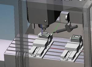
PartMaker is sold bundled with a graphic verifier that reads the part program and graphically simulates the entire cutting process, utilizing solid modeling techniques. This add-in allows the programmer to catch errors before expending machining time.
But what do all these features mean to the user? "PartMaker relieves you from the tedious process of reentering the same tooling and process information over and over again in every program," says IMCS/PartMaker Software president and founder Lena Fishman. "It allows shop personnel to benefit from the expertise of the most skilled programmer, who creates PartMaker's knowledge base." Mrs. Fishman sees the focus on tool management as an important trend in CAM software: "Historically, CAM systems' development was triggered by the need to program complex parts such as molds for jet engine blades. The majority of machined parts are not geometrically complex but do, however, often require multiple tools to perform repetitive operations. The affordability of powerful personal computers now makes it practical to shift the emphasis of CAM systems to handling tooling intensive jobs in a more efficient manner." And that, the company correctly asserts, addresses a very large portion of the time most shops spend on part programming. MMS
Related Content
TTI Brings Specialty Gear Production In-House with Multiaxis Machining
By investing in a 3+2-axis machine and utilizing simulation software for diagnostic checks, Techtronic Industries turned a four- to ten-week lead time into a one- to two-week lead time.
Read MoreHow Integrated CAD/CAM Transforms Inventions Into Products
The close connection between CAD and CAM is what links creative ideas to practical production for this unique custom manufacturer.
Read MoreLarge-Format Machining With Small Cutting Tools and Dynamic Motion
Napoleon Machine, a defense contractor that provides parts for the M1 Abrams tank, recently took advantage of a CAM feature that allowed the company to streamline its cutting strategies and program offline. Here’s how the shop cut cycle times nearly in half with its large-format five-axis machining operations.
Read MoreFive-Axis CAM Strategies Cut Cycle Time for Two Shops
After being acquired by the same parent company, two shops found that working together and sharing knowledge improved both of their bottom lines.
Read MoreRead Next
AMRs Are Moving Into Manufacturing: 4 Considerations for Implementation
AMRs can provide a flexible, easy-to-use automation platform so long as manufacturers choose a suitable task and prepare their facilities.
Read MoreMachine Shop MBA
Making Chips and Modern Machine Shop are teaming up for a new podcast series called Machine Shop MBA—designed to help manufacturers measure their success against the industry’s best. Through the lens of the Top Shops benchmarking program, the series explores the KPIs that set high-performing shops apart, from machine utilization and first-pass yield to employee engagement and revenue per employee.
Read More


